
 English English
 |


loading


The BSMJ Series Self-Healing Low-Voltage Shunt Capacitors are designed for 50/60 Hz AC power systems with a nominal voltage of 1000V or below. They are used to improve power factor, reduce reactive power loss in transmission lines, and enhance voltage quality.
The self-healing low-voltage shunt capacitors adopt metallized polypropylene film with excellent self-healing performance, incorporating advanced production technologies from both domestic and international sources.
They are produced in strict compliance with the national standards GB/T12747.1-2017, GB/T12747.2-2017 and the international standard IEC60831-1:2014. With an annual output of nearly 600,000 units, our company is one of the leading manufacturers of self-healing low-voltage shunt capacitors in China, boasting the largest production scale, most complete equipment, strong technical capabilities, and reliable product quality.
Superior Quality Assurance: Advanced production equipment, high-grade raw materials, and proprietary manufacturing processes ensure consistent high product quality.
Strong Environmental Adapt ability: A unique design enables the capacitor to operate reliably in environments with wide ambient temperature variations and significant system voltage fluctuations.
Integrated Safety Protection :Built-in discharge resistors and over pressure protection devices automatically disconnect the capacitor from the power supply if internal pressure rises or a fault occurs, preventing further accidents.
User-Friendly Installation & Connection :The innovative mounting plate allows for easy installation, while the specially designed terminals ensure convenient wiring, reliable connections, and excellent protection.
Compact & Lightweight Design :Small in size, light in weight, and elegant in appearance, the capacitor saves installation space and offers a sleek aesthetic.
· Tangent of loss angle:At power frequency rated voltage, tanδ≤0.0012 for capacitors of 30kvar and below; tanδ≤0.0015 for capacitors above 30kvar.
· Capacitance deviation:The difference between the measured and rated capacitance of the capacitor shall not exceed -5%~+10%. The ratio of the maximum to minimum capacitance measured between any two line terminals of a three-phase capacitor shall not be greater than 1.08.
· Withstand voltage Electrode to electrode: 1.15Un, 2s;Electrode to case: Apply 3.6kV for 5s to products with rated voltage of 600V and below; apply 7.2kV for 5s to products with rated voltage above 600V.
· Maximum allowable over voltage:1.1Un, with a duration not exceeding 8 hours in any 24-hour period.
· Maximum allowable over current:1.3In.
· Self-discharge characteristic:The capacitor is equipped with a discharge device, which can reduce the residual voltage from Un to 75V and below within 3 minutes after the power supply is disconnected.
· Ambient operating conditions:Ambient temperature: -25℃~+50℃.
· Relative humidity:≤50% RH at 40℃; ≤90% RH at 20℃.
· Altitude:For use at an altitude of 2000 meters and below.
· Executive Standards:GB/T12747.1-2017, GB/T12747.2-2017, IEC60831-1:2014
No. | BSMJ BCMJ BZMJ | Rated voltage KV | Rated capacitance kvar | Hz | μF | Rated current A | Shell Height H | Shell Type |
1 | 0.4-3-3 | 0.4 | 3 | 50 | 59.7 | 4.3 | H105 | Picture 3 |
2 | 0.4-5-3 | 0.4 | 5 | 50 | 99.5 | 7.2 | H115 | Picture 1 |
3 | 0.4-6-3 | 0.4 | 6 | 50 | 119 | 8.7 | H115 | Picture 1 |
4 | 0.4-7.5-3 | 0.4 | 7.5 | 50 | 149 | 10.8 | H115 | Picture 1 |
5 | 0.4-8-3 | 0.4 | 8 | 50 | 159 | 11.5 | H115 | Picture 1 |
6 | 0.4-10-3 | 0.4 | 10 | 50 | 199 | 14.4 | H130 | Picture 1 |
7 | 0.4-12-3 | 0.4 | 12 | 50 | 239 | 17.3 | H180 | Picture 1 |
8 | 0.4-15-3 | 0.4 | 15 | 50 | 299 | 21.7 | H180 | Picture 1 |
9 | 0.4-16-3 | 0.4 | 16 | 50 | 318 | 23.1 | H180 | Picture 1 |
10 | 0.4-18-3 | 0.4 | 18 | 50 | 358 | 26.0 | H220 | Picture 1 |
11 | 0.4-20-3 | 0.4 | 20 | 50 | 398 | 28.9 | H220 | Picture 1 |
12 | 0.4-25-3 | 0.4 | 25 | 50 | 498 | 36.1 | H230 | Picture 2 |
13 | 0.4-30-3 | 0.4 | 30 | 50 | 597 | 43.3 | H255 | Picture 2 |
14 | 0.4-32-3 | 0.4 | 32 | 50 | 637 | 46.2 | H255 | Picture 2 |
15 | 0.4-40-3 | 0.4 | 40 | 50 | 796 | 57.7 | H330 | Picture 2 |
16 | 0.4-45-3 | 0.4 | 45 | 50 | 896 | 65 | H230 | Picture 4 |
17 | 0.4-50-3 | 0.4 | 50 | 50 | 995 | 72.2 | H230 | Picture 4 |
18 | 0.4-60-3 | 0.4 | 60 | 50 | 1194 | 86.6 | H270 | Picture 4 |
19 | 0.45-3-3 | 0.45 | 3 | 50 | 47 | 3.8 | H105 | Picture3 |
20 | 0.45-5-3 | 0.45 | 5 | 50 | 79 | 6.4 | H115 | Picture 1 |
21 | 0.45-6-3 | 0.45 | 6 | 50 | 94 | 7.7 | H115 | Picture 1 |
22 | 0.45-7.5-3 | 0.45 | 7.5 | 50 | 118 | 9.6 | H115 | Picture 1 |
23 | 0.45-8-3 | 0.45 | 8 | 50 | 126 | 10.3 | H115 | Picture 1 |
24 | 0.45-10-3 | 0.45 | 10 | 50 | 157 | 12.8 | H130 | Picture 1 |
25 | 0.45-12-3 | 0.45 | 12 | 50 | 189 | 15.4 | H180 | Picture 1 |
26 | 0.45-15-3 | 0.45 | 15 | 50 | 236 | 19.2 | H180 | Picture 1 |
27 | 0.45-16-3 | 0.45 | 16 | 50 | 252 | 20.5 | H180 | Picture 1 |
28 | 0.45-18-3 | 0.45 | 18 | 50 | 283 | 23.1 | H220 | Picture 1 |
29 | 0.45-20-3 | 0.45 | 20 | 50 | 315 | 25.7 | H220 | Picture 1 |
30 | 0.45-25-3 | 0.45 | 25 | 50 | 393 | 32.1 | H230 | Picture 2 |
31 | 0.45-30-3 | 0.45 | 30 | 50 | 472 | 38.5 | H255 | Picture 2 |
32 | 0.45-40-3 | 0.45 | 40 | 50 | 629 | 51.3 | H330 | Picture2 |
33 | 0.45-45-3 | 0.45 | 45 | 50 | 708 | 57.7 | H230 | Picture4 |
34 | 0.45-50-3 | 0.45 | 50 | 50 | 786 | 64.2 | H230 | Picture 4 |
35 | 0.45-60-3 | 0.45 | 60 | 50 | 944 | 77.0 | H270 | Picture 4 |
36 | 0.48-5-3 | 0.48 | 5 | 50 | 69.1 | 6.0 | H115 | Picture 1 |
37 | 0.48-10-3 | 0.48 | 10 | 50 | 138.2 | 12.0 | H130 | Picture 1 |
38 | 0.48-15-3 | 0.48 | 15 | 50 | 207.3 | 18.02 | H180 | Picture 1 |
39 | 0.48-20-3 | 0.48 | 20 | 50 | 276.5 | 24.1 | H220 | Picture 1 |
40 | 0.48-25-3 | 0.48 | 25 | 50 | 345.6 | 30.1 | H230 | Picture2 |
41 | 0.48-30-3 | 0.48 | 30 | 50 | 414.7 | 36.1 | H255 | Picture 2 |
42 | 0.48-40-3 | 0.48 | 40 | 50 | 552.9 | 48.1 | H330 | Picture 2 |
43 | 0.48-50-3 | 0.48 | 50 | 50 | 691.1 | 60.1 | H230 | Picture 4 |
44 | 0.48-60-3 | 0.48 | 60 | 50 | 829.4 | 72.2 | H270 | Picture 4 |
45 | 0.525-5-3 | 0.525 | 5 | 50 | 58 | 5.5 | H115 | Picture 1 |
46 | 0.525-7.5-3 | 0.525 | 7.5 | 50 | 87 | 8.3 | H115 | Picture 1 |
47 | 0.525-8-3 | 0.525 | 8 | 50 | 92 | 8.8 | H115 | Picture 1 |
48 | 0.525-10-3 | 0.525 | 10 | 50 | 115 | 11.0 | H130 | Picture 1 |
48 | 0.525-12-3 | 0.525 | 12 | 50 | 139 | 13.2 | H180 | Picture 1 |
49 | 0.525-15-3 | 0.525 | 15 | 50 | 173 | 16.5 | H180 | Picture 1 |
50 | 0.525-16-3 | 0.525 | 16 | 50 | 185 | 17.6 | H180 | Picture 1 |
51 | 0.525-18-3 | 0.525 | 18 | 50 | 208 | 19.8 | H220 | Picture 1 |
52 | 0.525-20-3 | 0.525 | 20 | 50 | 231 | 22.0 | H220 | Picture 1 |
53 | 0.525-25-3 | 0.525 | 25 | 50 | 289 | 27.5 | H230 | Picture 2 |
54 | 0.525-30-3 | 0.525 | 30 | 50 | 347 | 33.0 | H255 | Picture 2 |
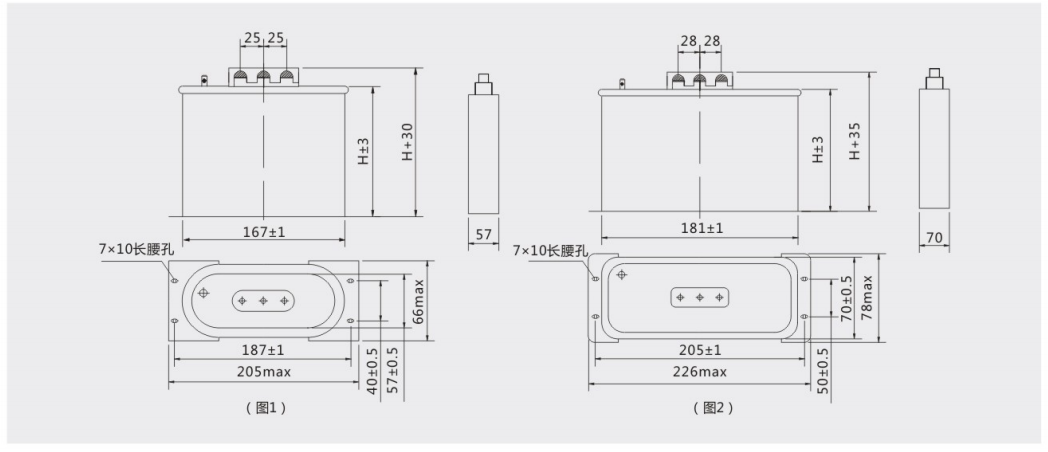
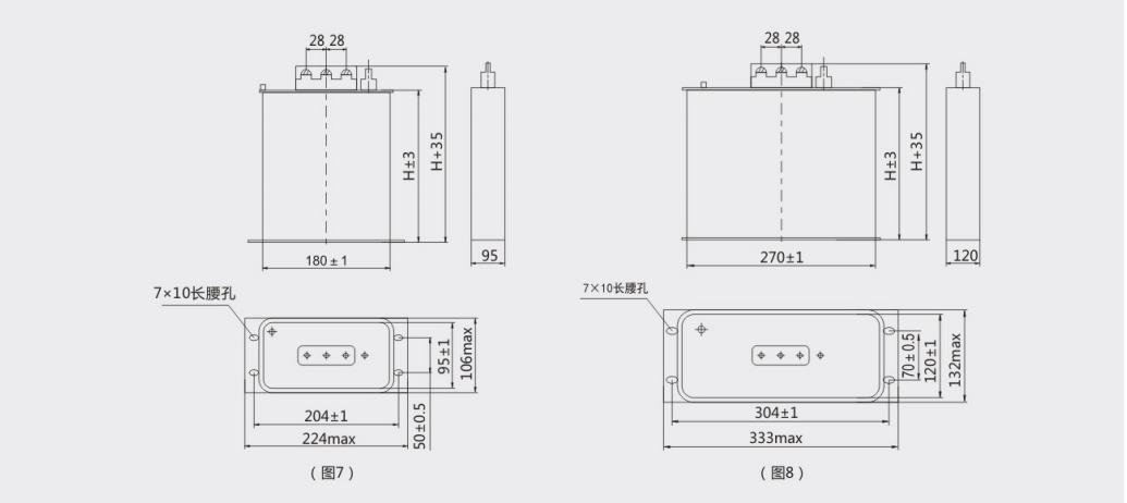
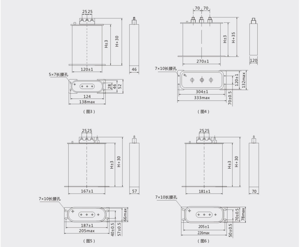
1. The capacitor shall be transported as far as possible in the original factory packaging and handled with care during moving.
2. The capacitor shall be stored indoors in a dry environment free of corrosive gas.
3. Before use, the user shall first check whether the model on the nameplate is consistent with the purchased product model.
4. Capacitance test: Comply with Clause 4 for the test; the measurement shall be conducted with an instrument whose relative error is not more than 2%.
5. Withstand voltage test: The applied test voltage shall be 4.3 times of 75% of the rated voltage.
6. The installation site shall be free of flammable gas, protected from rain and snow, and away from areas with excessive dust and severe vibration. The distance between capacitors shall be more than 30mm. When the ambient temperature is high in summer, effective measures shall be taken to ensure good ventilation and heat dissipation.
7. Before installation, factors such as voltage rise caused by the capacitor operation must be considered to prevent the capacitor from long-term operation under over voltage.
8. Before installing the capacitor, attention must be paid to the grid voltage and harmonic characteristics. If affected by harmonic sources (e.g., large rectifiers, frequency converters, medium frequency furnaces, electric arc furnaces, electrolysis and electroplating equipment, etc.), corresponding measures shall be taken to suppress harmonics according to their frequency and content.
9. When the capacitor is connected in parallel with an induction motor, it is recommended to select the capacitor with a capacitance less than 90% of the no-load current of the motor.
10. Flexible copper wire shall be used as much as possible for the grounding wire at the grounding terminal of the capacitor circuit to ensure good contact. It is recommended that the user inspect the capacitor terminals regularly to prevent capacitor damage caused by poor contact.
11. The time interval between capacitor switching-off and re-switching-on shall be more than 3 minutes (self-discharge time), otherwise high over voltage may occur and damage the capacitor. A dedicated capacitor switching switch shall be used for the capacitor, and the switch specification shall be determined with reference to the range of 1.5–1.9 times the rated current of the controlled capacitor.


